On this page
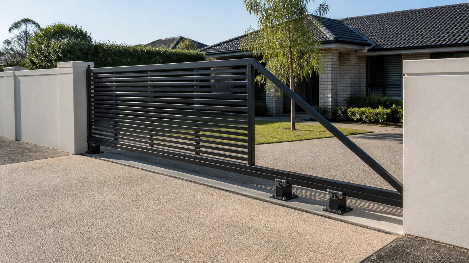
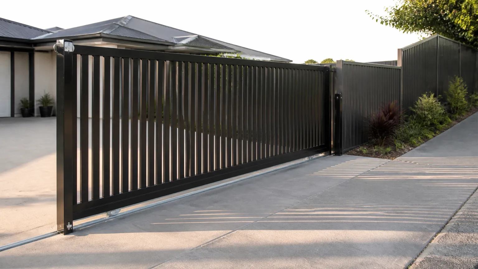
A tracked sliding gate is a frame on wheels that rolls along a track in the ground. The build is simple, but the parts have to suit each other. If the wheel does not fit the track, or the track is not level, the gate fights you every time it moves.
This guide runs through a tracked gate in the order you would build it: measure, track, frame, wheels, posts, stops and motor prep. It assumes an aluminium frame. For a gate with no track at all, see the cantilever gate tail guide.
What you need to know
- You need clear run-back beside the opening at least as long as the gate.
- The track sits on a level concrete strip that runs the full travel of the gate.
- Match the wheel groove to the track: V groove on V track, round groove on round bar.
- A guide post with rollers holds the top. A catch post takes the closing end.
- If a motor is coming, plan the rack, the pad and the cable before you pour.
How much space does a sliding gate need?
Start with the clear opening: post face to post face, where the car drives through. The gate is wider than that. It overlaps the fence or post at each end so there is no gap when it is shut. CAD60 starts at 50 mm of overlap each side, and you can change it.
Then check the run-back. That is the space beside the opening where the gate parks when it is open. It has to be at least as long as the gate, plus room for the end stop. A 5 m opening with 50 mm overlaps makes a 5.1 m gate, so you want more than 5.1 m of clear, level run-back.
Look along the run-back for anything in the way: letterboxes, taps, garden beds, a step in the ground. If the driveway slopes across the opening, read measuring sliding gates on raked ground first. The track has to stay level even when the ground does not.
How do you set out the track?
The track sits on a concrete strip that runs the whole travel of the gate: across the opening and along the run-back. One build guide gives the strip as 100 to 120 mm deep. Width depends on the track base and the fixings. The strip must be level along its length. Any hump or dip shows up as a gate that rolls open on its own or sticks halfway.
String a line for the track
Run it from the catch post to the far end of the run-back, set to the gate's line.
Pour the strip level
Check it with a long straight edge and a level. Fix any dip now, not after the track is down.
Fix the track down
Dynabolts or chemical anchors at even centres. Run the track a little past each end of the gate's travel for the end stops.
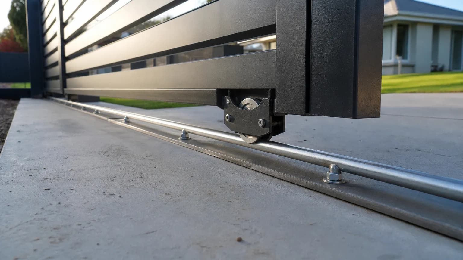
Three track shapes are common for tracked gates. A round bar welded to a flat base. An inverted V track made from angle. And a U channel the wheel runs inside. CAD60's tracked gates start with a 16 mm round bar on a 50x6 flat. The sliding gate track types guide compares them all.
What frame does a sliding gate need?
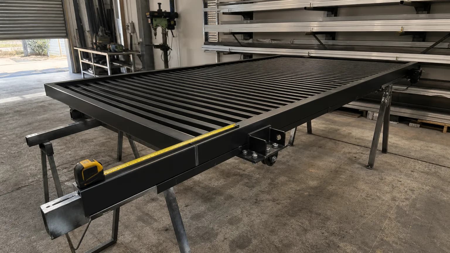
A sliding gate frame is a rectangle: two stiles, a top rail and a bottom rail. The bottom rail carries all the weight on the wheels, so it is the deepest member. CAD60 starts a tracked gate with 50x50x3 SHS stiles and top rail and a 100x50x3 RHS bottom rail. Treat that as a starting point, not a rule. A long or heavy gate wants more.
Long gates often get mid rails to stop the infill bowing and to stiffen the frame. Then the infill goes on: battens, slats, louvres or sheet. Keep the bottom of the infill clear of the wheels and track. The gap under the gate has to hold both. CAD60 starts at 60 mm.
Weld the frame flat on a table and check both diagonals before the final welds. A twisted sliding gate rubs on its guide rollers for the rest of its life. The aluminium gate welding guide covers sequence and distortion, and RHS vs SHS for gate frames explains why a deeper bottom rail beats a thicker wall.
How many wheels does a sliding gate need?
Two, set in from each end of the bottom rail. CAD60 starts them 300 mm in from each end. A long or heavy gate can take more, spaced evenly between the two end wheels.
The groove in each wheel must match the track. A V groove wheel runs on a V track. A round groove runs on round bar. A flat or U groove runs in a channel. Put the wrong wheel on the wrong track and it rides on a point. It wears fast and jumps the track.
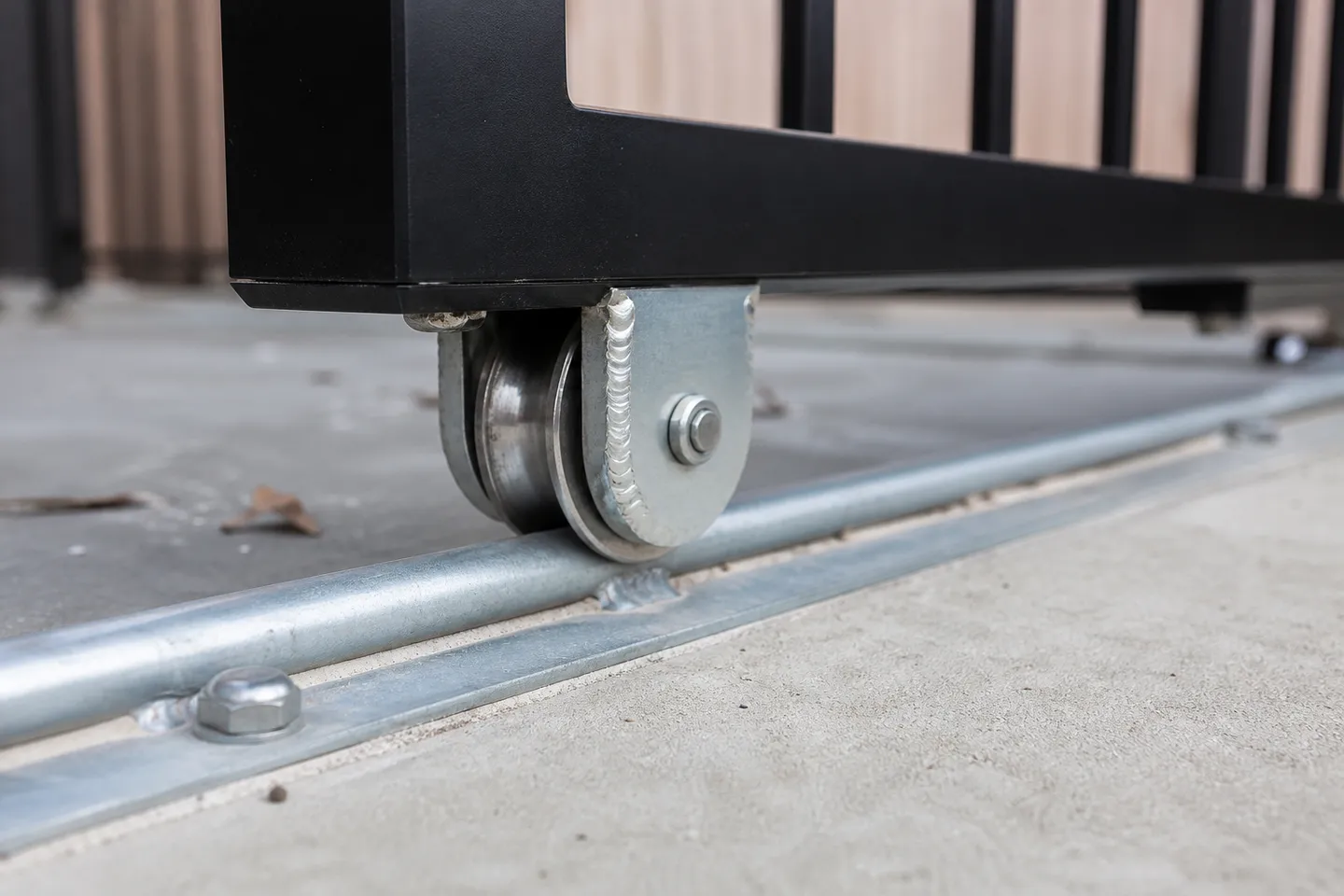
There are two ways to mount the wheels:
- Bracket under the rail. Two cheek plates welded under the bottom rail, one each side of the wheel, with an axle through them. Easy to fit and to swap.
- Axle through the rail. The wheel sits up inside a slot in the rail, so the gate sits lower. More cutting, but a tidier look.
What holds a sliding gate upright?
The wheels carry the weight. They do nothing to stop the gate falling over. That is the job of the guide post. It stands at the run-back edge of the opening, behind the gate, and carries a bracket with guide rollers one each side of the top rail. The gate slides between them.
At the other end is the catch post. It has a receiver that takes the leading end of the gate when it shuts. That holds the closed gate against wind and pushing.
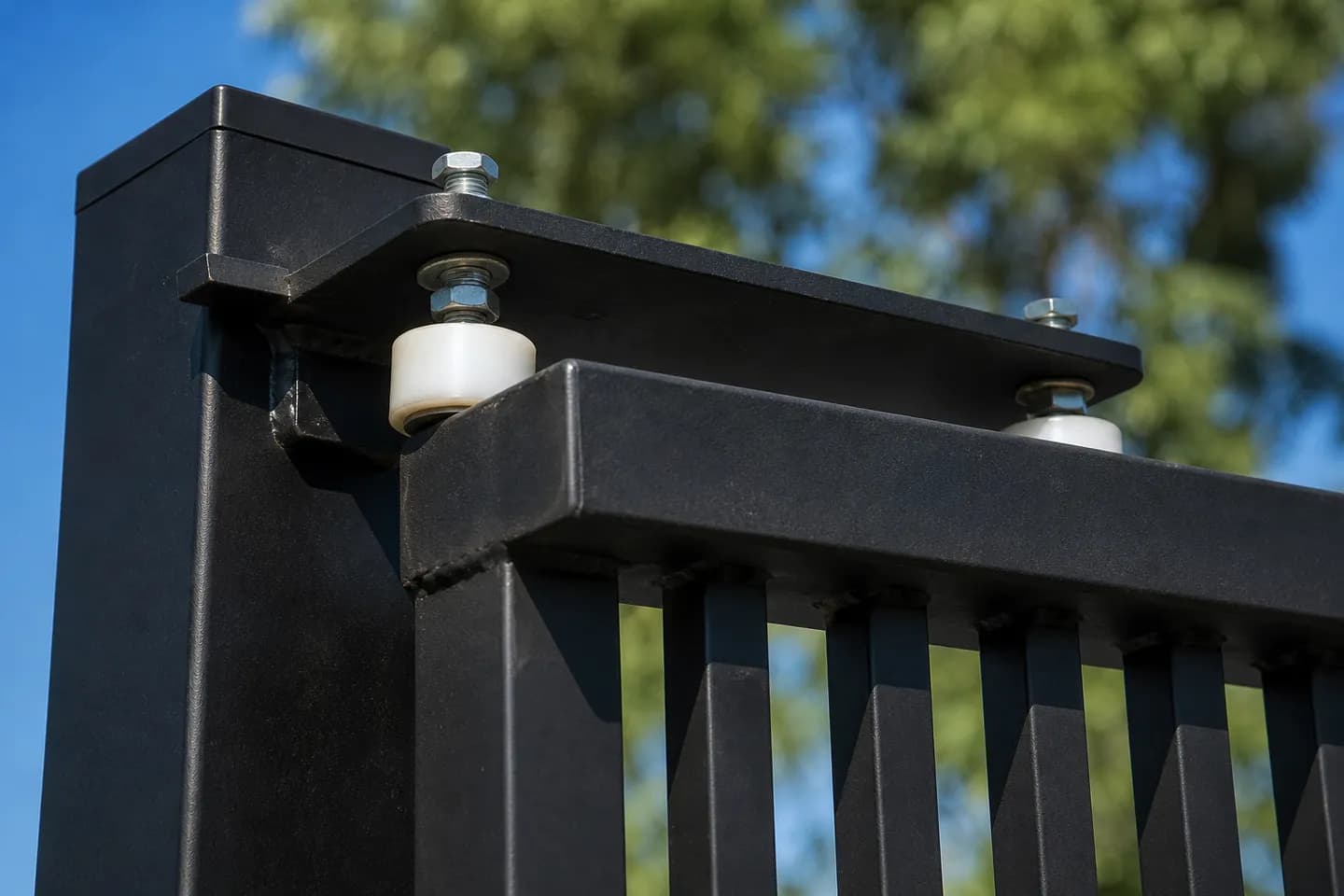
CAD60 starts both posts at 75x75x4 SHS with 600 mm in a concrete footing. Size them for your gate and your ground. Set the guide rollers with a few millimetres of clearance to the gate. Too tight and it binds. Too loose and it rattles. The gate post size guide goes deeper on post choice.
Where do the stops go?
Fit an end stop at each end of the gate's travel. One stops the gate rolling off the open end of the track. The other stops it at the closed position. Without them, a gate that is pushed hard can roll off the end and fall.
Many installers also fit an anti-lift bracket at a post, so nobody can lift the gate off its track from outside.
| Part | Where it goes | What it does |
|---|---|---|
| Track | Level strip, full travel | Carries the wheels |
| Wheels (2 or more) | Under the bottom rail | Carry the weight |
| Guide post and rollers | Run-back edge of the opening | Hold the top upright |
| Catch post and receiver | Closing edge of the opening | Take the leading end when shut |
| End stops | Each end of travel | Stop the gate rolling off |
How do you get a sliding gate ready for a motor?
Even if the motor is not going in yet, a little planning now saves a lot of cutting later.
- Pick the motor first. Its manual tells you where it sits and how high the gear rack must be.
- Leave the rail face clear. The rack bolts along the bottom rail. Set the battens or slats up off the rail face so the rack has somewhere to go.
- Pour the motor pad with the strip. Put conduit for power and controls in before the concrete goes in.
- Check the gate reaches the motor. With the gate shut, the rack has to run past the motor's pinion. Some gates need a short tail past the opening to get there.
Put it all on the drawing: the opening, the overlaps, the wheel positions, the track, the posts and the rack height. The sliding gate shop drawing guide lists what to include.
Common questions
Do you need a concrete strip for a sliding gate track?
Yes. The track needs a solid, level base along the full travel of the gate. A track fixed to pavers, gravel or an uneven driveway moves and dips, and the gate starts to roll on its own or stick.
Can a sliding gate go on a sloping driveway?
The track itself must be level, or the gate will roll downhill. On a slope you set the track level and shape the gate to the ground, or you choose a cantilever gate, which has no track across the opening.
How much bigger than the opening is a sliding gate?
A tracked gate is the opening plus an overlap at each end. CAD60 starts with 50 mm each side, so a 4 m opening gives a 4.1 m gate. Some builders use more overlap to suit the catch post and receiver.
What is the gap under a sliding gate?
It is the room the wheels and track need, plus a little air. CAD60 starts at 60 mm from the ground to the underside of the gate. Bigger wheels or a taller track need more.
Should the guide rollers touch the gate?
No. Leave a few millimetres each side. Rollers set hard against the gate make it bind and wear. Rollers set too far away let it rock and rattle in the wind.
Is aluminium good for a sliding gate?
Yes. An aluminium gate is light, so it is easy on the wheels, the track and a motor, and it will not rust. Use a deep bottom rail, as aluminium tube flexes more than heavier metal of the same size.
Written by Harry Tolley
Harry builds CAD60 with his dad, who has run a fabrication business for 20 years. We write these guides from what goes wrong in a real shop.